|
HALL EFFECT 24 VOLT DC SYSTEM
Building a basic test circuit using
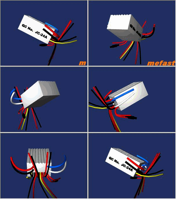
General Replacement JC-24A Controller |
|
HALL EFFECT SPEED CONTROLLER ( DERAILLIEUR ) |
HALL EFFECT
JC-24A 24 VOLT OUTPUT CONTROLLER |
MY1016 24 VOLT 250 WATT MOTOR
 |
|
BRAKE HANDLE
|
12 VOLT BATTERY
|
KEY SWITCH
|
LOCK CONNECTION
|
Lock connector
Connection to key switch
w/10 volt fuse protect Activates Controller |
||||
|
24V Max Output
connector to MY1016 motor Power to motor |
BASIC TEST CIRCUIT |
Accelerator connector Hall effect accelerator input connection Throttle Input to controller ( If system wire is green attach to yellow) |
||
|
24 Volt Battery Connector
24 Volt to controller |
||||
|
24 Volt series connection
|

Use caution, do not cross polar sensitive circuits on battery, charger
If the basic test circuit is running the motor you can connect the other circuits.
CHANGING CONNECTORS
Connectors may be hard-wired or reconfigured using existing pins.
You may use your the scooter connectors but be aware male and female pins are different.
The pins at the end of each wire may be pushed out of the connector on the controller and scooter connectors.
Connectors may be hard-wired or reconfigured using existing pins.
You may use your the scooter connectors but be aware male and female pins are different.
The pins at the end of each wire may be pushed out of the connector on the controller and scooter connectors.
|
PILOT LAMP
This is the headlight connection.
|
CHARGER
This circuit is a polar sensitive, be sure black is negative, black is not a ground. |
|
BATTERY Polar sensitive connection. Be sure red connects to positive.. |
MOTOR 24v motor connection. If motor rotates backward reverse connection. |
|
STOP LIGHT This is the connection that leads to the tail light. |
||
LOCK circuit This is the connection with the fuse holder. Connects to on/off toggle or key switch. |
||
DERAILLEUR This is the throttle / accelerator connection. Connect red to red, black to black . Your scooter will have a green or yellow wire connect this wire to the yellow controller wire. |
||
CHARGER 24 Volt Charger Input This circuit is polar sensitive. |
||
| . |
BRAKE This circuit is activated by the brake handle, when active motor is disabled and power is sent to the brake light |
XYK-2000-24
This unit will replace XYK-2000-24 for two wheel scooters. Negative motor wire must be connected to controller as above and not to battery negative.
This unit will not replace XYK-2000-24 with relay (high / low) and double relay (reverse and forward) for three and four wheel scooters.
This unit will replace XYK-2000-24 for two wheel scooters. Negative motor wire must be connected to controller as above and not to battery negative.
This unit will not replace XYK-2000-24 with relay (high / low) and double relay (reverse and forward) for three and four wheel scooters.

Get the book
Get the schematic
Get a wire diagram
mefast.com
